For device assembling, you will need the next components:
- Arduino Mega 2560 controller board
- Ethernet module: Arduino Ethernet Shield or ENC28J60 Ethernet module or Wi-Fi module based on ESP8266 chip
- Optionaly up to 2 DS18B20, DS18S20, DS1822 temperature sensors
The connection diagram of Arduino Mega 2560 controller board, temperature sensors and input/output ports position is shown below.
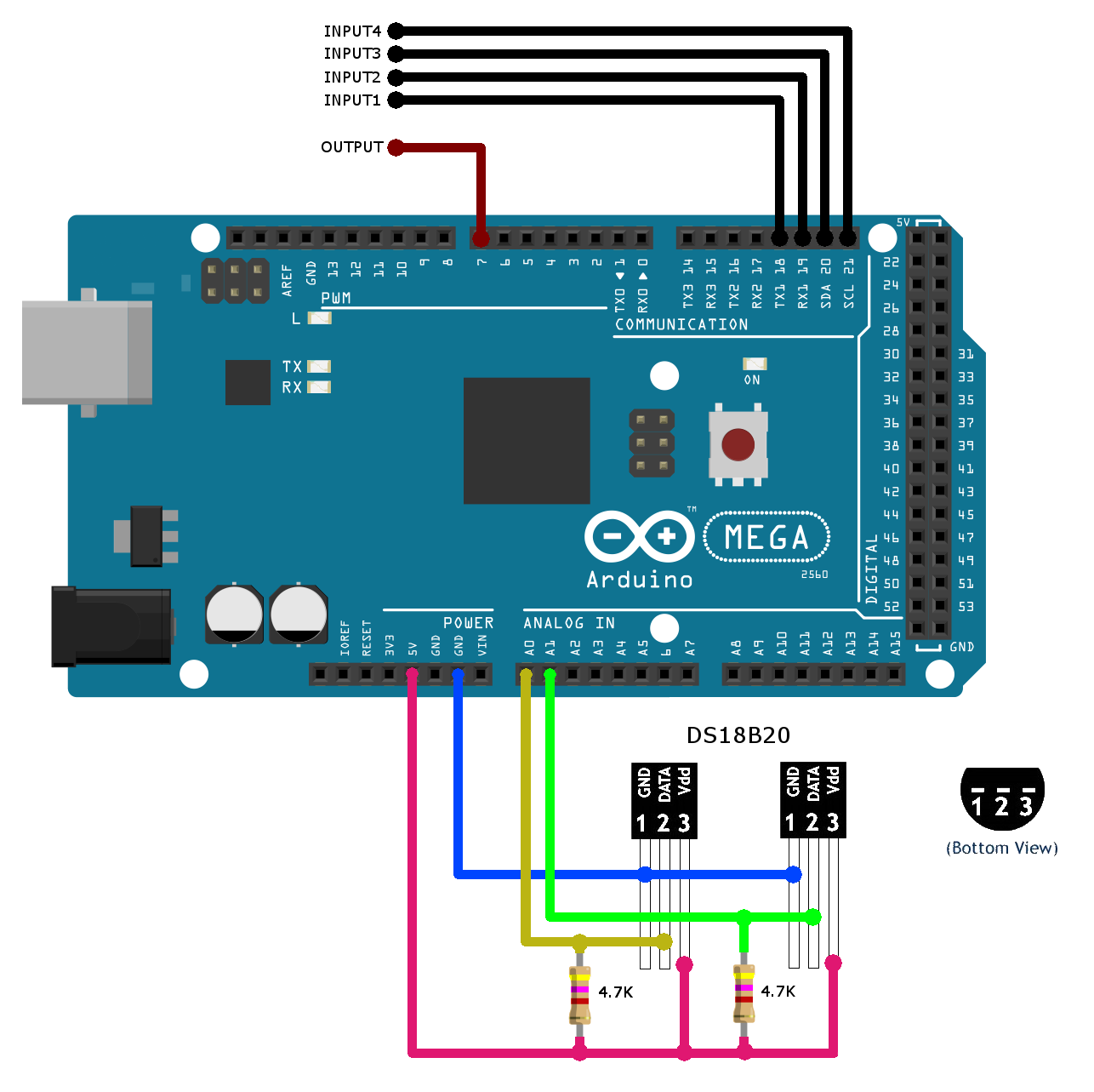
By default is used current writing diagram of ports connection:
- Input ports: D18-D21, GND
- Output ports: D7, GND
- Temperature sensors: A0, A1, 5V, GND
You may change port position to your notice:
- Input ports: 2, 3, 18, 19, 20, 21.
- Output ports: all available digital pins.
- Temperature sensors: all available digital pins.
NotifyDuino support next ethernet modules:
1) Wi-Fi module based on ESP8266 chip, for example ESP-01.
The connection diagram of Arduino Mega 2560 controller board and ESP-01 module is shown below
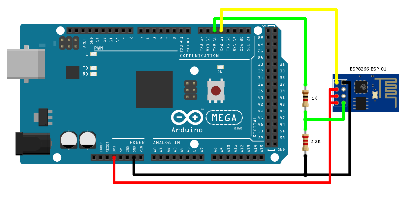
ESP8266 module is not 5V tolerant. It works on 3.3V power supply. To convert 5V output of Arduino TX to 3.3V input level use simple resistor divider. Arduino baud rate for communication with ESP-01 module is 115200.
2) ENC28J60 Ethernet module.
The connection diagram of Arduino Mega 2560 controller board and ENC28J60 Ethernet module is shown below
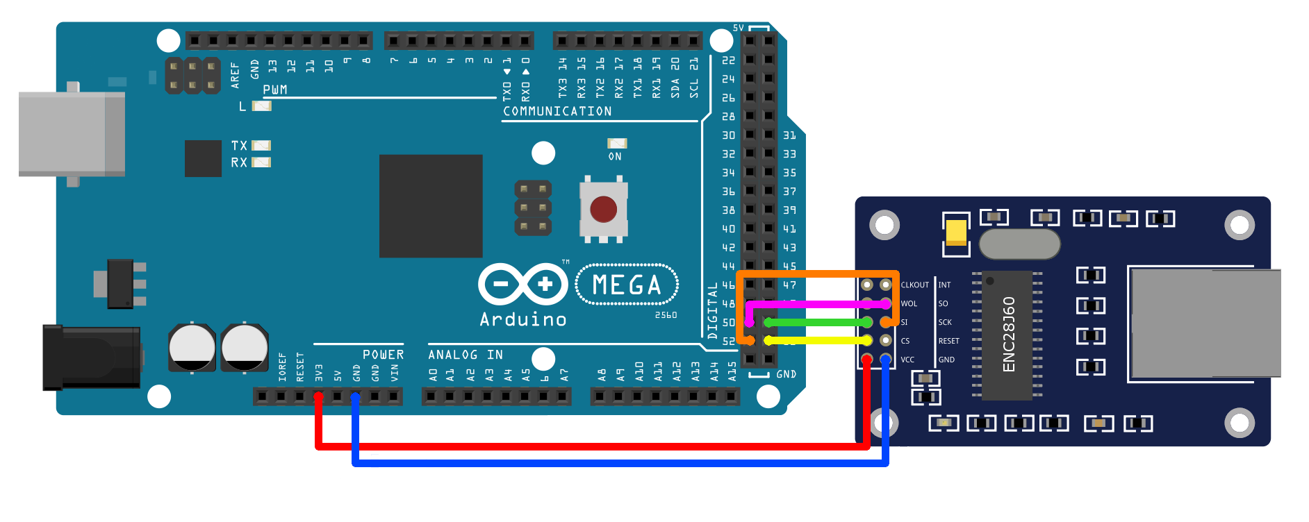
ENC28J60 Ethernet module:
| Arduino Mega 2560 | ENC28J60 module |
|---|---|
| D53 | CS |
| D51 | SI |
| D50 | SO |
| D52 | SCK |
| 3V3 | VCC |
| GND | GND |
3) Standart Arduino Ethernet Shield based on W5100 chip.
Old revison don't support Arduino Mega board, so check it before using. For more information see https://www.arduino.cc/en/Main/ArduinoEthernetShield
Download and install:
- Download and install Arduino IDE.
- Download project on GitHub.
- Install required libraries which are located in «libs» folder or from following links:
- UIPEthernet - https://github.com/ntruchsess/arduino_uip (If you don't use ENC28J60 Ethernet module, you no need to install this library)
Set up your device parameters in "UserSettings.h" file:
- Enable debug information in serial monitor. Default baud rate 115200, Enable only for testing, disable for normal usage.
DUINO_SERIAL_DEBUGGING 0 - Disable debugging
DUINO_SERIAL_DEBUGGING 1 - Enable debugging
- Select network module.
NETWORK_INTERFACE 1 - Standart Arduino Ethernet Shield, W5100 chip
NETWORK_INTERFACE 2 - ENC28J60 Ethernet module
NETWORK_INTERFACE 3 - Wi-Fi module based on ESP8266 chip, ESP-01
- Set up the network device parameters.
For Arduino Ethernet Shield or ENC28J60 Ethernet module only.
Set up following parameters, actual for your device:
default_mac[6] 	    = { 0xFC , 0xC2 , 0x3D , 0x4C , 0x4B , 0x40};
default_ip[4]	 	= { 192, 168, 10, 113 };
default_gateway[4] 	= { 192, 168, 10, 1 };
default_mask[4] 	= { 255, 255, 255, 0 };
default_dns[4]   	= { 8, 8, 8, 8 };
After connecting the device to Android app, can be replaced network settings through it.
For Wi-Fi module based on ESP8266 chip set up following parameters:default_AP_SSID = ""; // Local Wi-Fi network name (SSID) default_AP_PSW = ""; // Local Wi-Fi network password (PSW)
- Changing the device ports order
If you want to use port for input signal different from default, or want to connect temperature sensors to other controller ports, that need to make next changes.
Input ports and messages (available ports - 2, 3, 18, 19, 20, 21):inputPin1 = 18; event1Message = "Pin 18 changed ..."; inputPin2 = 19; event2Message = "Pin 19 changed ..."; inputPin3 = 20; event3Message = "Pin 20 changed ..."; inputPin4 = 21; event4Message = "Pin 21 changed ...";
Output port (available ports - all available digital pins):outputPin = 7;
Temperature sensor ports (available ports - all available digital pins):TempSensor1Pin = A0; temp1EventMessage = "Temperature 1 out of range !!!"; TempSensor2Pin = A1; temp2EventMessage = "Temperature 2 out of range !!!";
Appload source code into controller board:
- Plug the controller board to PC
- In Arduino IDE choose board model (Tools - Board - Arduino/Genuimo Mega or Mega 2560)
- Open «NotifyDuino.ino» file, and download the firmware in controller, press Upload button
Unique device serial number.
When launching sketch at the first time, occurring the generation of random 29-bit serial number.
Device serial number necessary for registration your device in Android application.
In order to receive device serial number, open serial monitor in Arduino IDE, set up baudrate to 115200 and reset device.
After connecting controller to the ethernet you can control it through web typing controller ip in webbrowser or you can control it through android application, also it allow receive GCM messages from controller to your android device in any place.
App for Android device, you can download here
NotifyDuino.apk
Application settings description, you can find by link NotifyDuino manual